|
||
|
Home << Product Main << PTZ Varifocal Cam Main << EPC-200 |
||
|
Installation Guide of #EPC-200 |
||
|
|
||
|
|
||
|
Click pictures to view the enlarged version... |
||
|
|
||
|
|
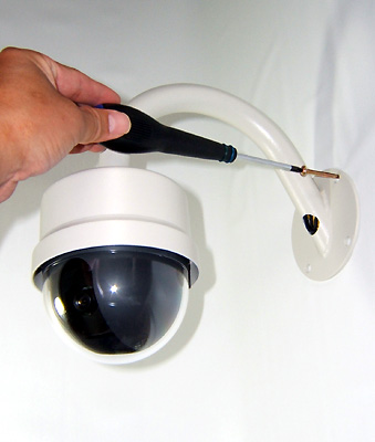
1. Screw the wall mount bracket using all four screws included and go to step 4 if you purchased the camera in outdoor wall mount housing. |
|
|
|
||
|
|
2. For the camera without outdoor housing to be installed directly on the flat surface, simply affix the whole camera using four screws included as it shown on the left picture and go to step 4 for wiring procedure. |
|
|
|
||
|
|
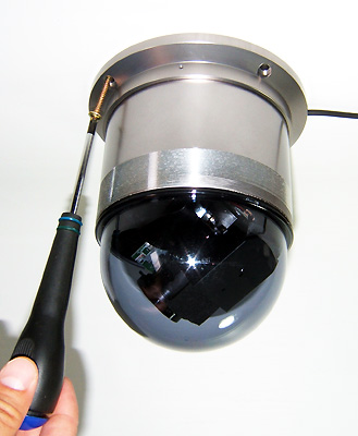
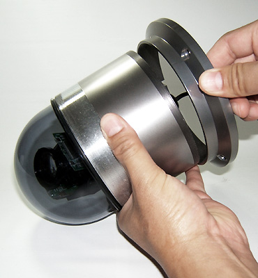
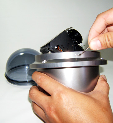
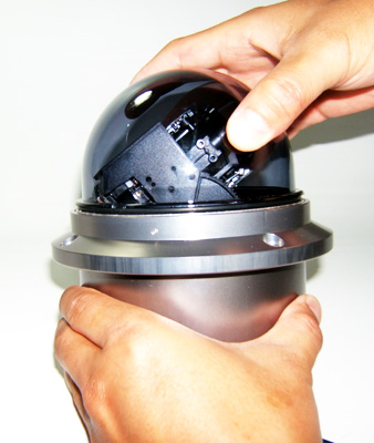
3. For the camera without outdoor housing and camera body portion to be installed hidden behind ceiling or wall as method of the flush mounting, use Allen wrench to loosen the bracket ring and unscrew to apart from the bottom portion of the camera body. Then unscrew the dome cover and screw the bracket ring that removed from the bottom portion onto the upper portion of the camera body all the way until it stops screwing. |
|
|
|
|
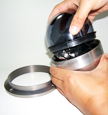
Make sure to secure the screwed bracket ring firmly using Allen wrench and screw back the dome cover. |
|
|

|
Make a hole which diameter is slightly enough to insert the camera body on the ceiling or wall and affix the camera screwing all four around the bracket ring after inserting the camera body. |
|
|
||
|
|
Further
installation steps are both
for the camera with or without outdoor housing. |
|
|
|
||
|
|
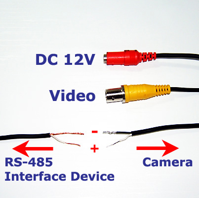
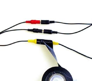
5. Wiring connection should be as it shown on the left picture as Red for DC-12V, Yellow for Video, and Black for IR Converter included or any other RS-485 communication interface device. |
|
|
|
||
|
|
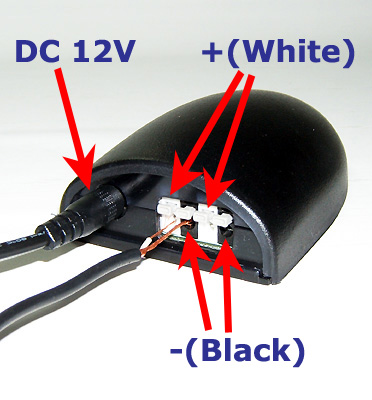
6. Connect the other end of the extension cable as Yellow to Video-in on the recording device and Red to the included 12V power transformer or your own 12V power source. Then split the black wire into two + & - and connect them to the back of IR Converter included as it shown on the left picture or any other RS-485 communication interface device. Be sure always to locate the IR converter near the display monitor connected to system for it to be controlled the remote control wirelessly looking at the monitor. |
|
|
|
||
|
|
7. Connect the other end of the cable to the outcome display monitor either directly from the camera or recording device (if the camera is connected via) as the connection procedure explained on 5 and power up all equipments that connected the system. |
|
|
|
||
|
|
8. Power up the remote control unit inserting two AAA batteries included and aim to the IR converter to control the camera wirelessly. Don't forget to power up the IR converter as well with the included DC-12V power supply. |
|
|
|
||
|
|
9. When the monitor location is out of viewable range from the camera, one more persons be needed to assist on correcting the camera-viewing angle, tilt, or pan adjustment while the other person is adjusting the actual camera angle at the camera location. |
|
|
|
||
|
|
10. At last, make sure to wrap around all cable connections securely with the electrical tape when wirings going through outdoor and intended to leave outdoor for long time. |
|
|
|
||
|
|
||
|
|
||
|
Home | About Us | Contact Us | Tech-Support | Product | Directory |
||
|
|
||
|
|
||